Have you ever wondered how skilled operators in the UK Manufacturing industry harnessed their skill in Metal Spinning? Presumably, you’re here to learn more about the Metal Spinning process and the steps involved to produce magnificent, hollow cylindrical components.
In our Ultimate Guide to Metal Spinning, we took you through what Metal Spinning is. We also explored three methods of metal spinning that manufacturers adopt to produce a vast array of products and components. In this guide, we will run you through a step-by-step guide to the Metal Spinning Process.
Sound good to you? Then let’s get started!
What You Will Need In Metal Spinning
During this guide, we will be covering the art of manually hand spinning using conventional methods. This process involves the body of the spinner and the result of the process is heavily impacted by the skill of the operator (as with any hand forming process). At Excell Metal Spinning Ltd., our operators have over 200 years experience combined between them!
If you need more guidance on what Metal Spinning is, or you quickly want to learn more about conventional metal spinning, then read The Ultimate Guide To Metal Spinning (With Diagrams).
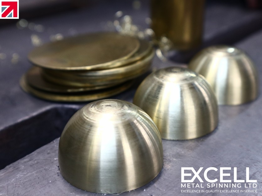
In the first attempt, we recommend practicing metal forming a flat-bottomed cylinder, roughly 50.8mm in diameter and 76.2mm high. This will require a 127mm diameter disc and a mandrel (commonly referred to as a ‘chuck’) that you will form the disc over.
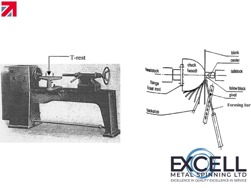
You will also require a manual Metal Spinning Lathe that you will use to carry out the conventional metal spinning process. Refer to Figure 1.0 to observe what a typical hand spinning lathe would look like.
In our next guide, we will explore the different variations of chucks and spinning tools that highly skilled operators use during the metal spinning process.
In Figure 1, Wong, Dean & Lin (2003) identify a spinning lathe used by Manual Hand spinners.
Setup
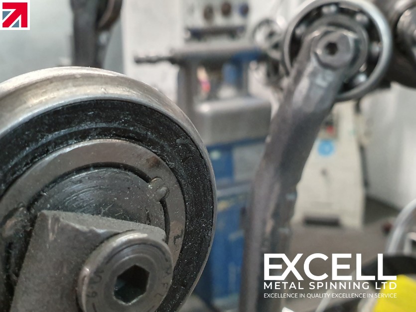
After the mandrel has been carefully selected, it should then be screwed into place over the threaded head-stock spindle as observed in Fig 1. By turning the lathe on, you can determine if the chuck is running true.
There are many possible causes for the chuck to not run true and these include;
- The Mandrel / Chuck has been used on another lathe with or without an adaptor
- The Mandrel is Warped
- The Mandrel is Damaged
- The threads may be worn and therefore require reseating
A clamp, or block, should be attached to the tail stock spindle, ensuring the diameter of the block matches with the bottom of the mandrel. It’s important it matches as this could have adverse consequences should it not. Too small, and the bottom of the spinning will buckle during the process; Too large, and the spinning will not have proper contact with the mandrel.
Metal Spinning Lathe RPM
Speed plays an important role throughout the metal spinning process. The general rule of thumb for most spinning operations will use a lathe speed anywhere between 800 to 1800 RPM. The larger the thickness or diameter the slower the RPM.
There are times when parts initially begin as thin discs which can be spun with speeds as high as 5,000 RPM, and on other occasions around 100 RPM for huge discs. It is important to identify the correct RPM to avoid wrinkling the material or burning out lubricant. Too slow an RPM, will result in hardening, tearing or misshapen parts.
Centering A Disc On A Spinning Lathe
At the beginning of the spinning process, the metal disc is clamped between the mandrel and the block attached to the tailstock. It is important to closely center the disc as possible. However, the likelihood of further centering is high.
A centering tool (more will be explained in another blog) is a useful tool operators use for this occasion. These tools can range from a hardwood flat stick, a flat faced spinning tool or the flat part of a tongue spinning tool.
The operator would hold the centering tool within their left hand, whilst the tool rests against the pin on the T-rest. Refer to figure 1 for the location of the T-rest and pins. With the disc’s rotation at a right angle to the face of the tool and the axis of the tool in the same plane, centering can take place. The contact between the tool and the edge of the disc is performed underneath and towards the front of the disc (in a 7 o’clock position).
The operator holding the centering tool stands to the right and controls the tail block pressure with their free right hand. The follow block is loosened slightly whilst the lathe is running an the centering tool is pushed up against the disc until vibrations cease. The tool block is then finally tightened and the centering tool is no longer required.
Metal Spinning Tip – Correcting Centering Errors
"Note – should the disc fly out of control in a worse case scenario, or even become off centered, the operator would pull the centering tool away and release the tailstock spindle pressure. The disc will jump from the lathe, which is dangerous and enforces the need for correct PPE to be worn at all times. Although purposely allowing the disc to jump from the lathe is dangerous, it is less so when the disc jumps without warning and potentially injuring an unaware operator."
The velocity is decreased when the follow block pressure is released, and will usually result in the disc falling rather than flying out of control.
How To Metal Spin
The beginning of the spinning process is often the most critical, and with the help of a spinning tool, its important the center of the disc is fixated around the mandrel. In doing so, the next set of strokes of the spinning tool can accurately smooth out any warps and ensure the disc remains even.
The spinner will use a ‘sweeping’ / radial motion to form the disc over the mandrel. They do this by holding the tool under their arm, and using the force from their shoulder, rib cage and lowered hip, as well as flexed knees and feet firmly flat on the ground. The tool will rest against the pin on the T-Rest, and the tip of the tool will be positioned to the right of the disc against the follow block at 7 o’clock.
As the body position of the operator stretches upwards, the tip of the tool drops in a small arc from the follow block to the edge of the disc, just like a sweeping motion, and again at 7 o’clock. The force of the ‘sweeping’ arc of the tool is in one lateral movement towards the headstock. With a combination of moving the upper body towards the right, and the unequal flexing of the knees, the spinner will exert enough force to form the disc over the mandrel. It will require multiple passes to full form the metal disc over the mandrel.
Metal Spinning Tip – Feathering Strokes
“A Feathering stroke is when the stroke of the tool is swept out to the edge with diminishing pressure. This is so that, by the end of the stroke, there is no pressure at all. Short strokes, in a back and forth sweep ‘feathered’ stroke, will ensure the elimination of minor wrinkles in the metal. It can also help with over stretching or folding back of the material.”
In the final stage of the spinning process, a flatter spinning tool can be used. The operator would then use firm, even strokes to lay down the remainder of the metal disc whilst increasing the section.
The final stroke is performed with as flat a tool as possible and apply a ‘Planishing’ stroke. Read “The Ultimate Guide To Metal Spinning” to learn more about Planishing.
Trimming A Metal Spinning
Depending on the project, trimming may be required to even out the component, which may have been distorted around the edge. A useful tip is to perform the final trim just before the final flap is laid down. This will help with any parts shorter than what the mandrel was designed for!
Operators would use a ‘Trimming’ Tool, which is a square shaft of steel cut diagonally around one edge. Again, resting the tool against the pin on the T-rest, and bring the edge of the tool to the edge of the disc will ensure precise trimming.
It is even more so important the correct PPE is worn at all times throughout the spinning process and the trimming of metal spun components.
How To Remove A Finished Metal Spinning From The Lathe
It is equally important to know how to remove a metal spinning from the mandrel. This can be done whilst the mandrel is still moving or still, and both will require the loosening of the tailstock spindle.
There are times however, when a cylindrical part stayed in close contact with the mandrel with no spring-back and thus formed a vacuum inside. A final planishing stroke with the forming block removed from the piece can help remove the component from the mandrel (from left to right).
Some metal spinner, when possible, opt to drill a small in the disc before spinning. This will help avoid a vacuum and make it easier to remove the spinning from the mandrel.
It should also be noted that any backward tapers on the mandrel could lock the component to the mandrel. If an operator finds themselves in the position of a component stuck to the mandrel because of this, application of heat can be used as a solution to expand the metal part for easier removal. This will increase the likelihood of charring of the chuck in the worst case scenario.
Use Metal Spinning In Your Supply Chain
With an efficient process of manufacturing at your disposal, you can drive down cost and increase your margins. Metal Spinning is now widely accepted as an efficient manufacturing process that has a higher material utilization and low cost production ideal for batch production.
As a leading expert in the field of Metal Spinning, and the leading organization in the UK Metal Spinning Industry, Excell’s services have been widely sought after worldwide. With the vast skills and knowledge required, we can ensure quality products are delivered on time and to your requirements!
To get started on your next project with us, and to determine the best possible solution for your industry needs, you can fill out a Quotation Form. Our team are on hand ready to help you!
References
Wong, C. C., Dean, T. A., & Lin, J. (2003). A review of spinning, shear forming and flow forming processes. International Journal of Machine Tools and Manufacture, 43(14), 1419-1435
Find out more about Excell Metal Spinning Ltd on their member profile page here
Member-created content 4 years ago | From members